


-
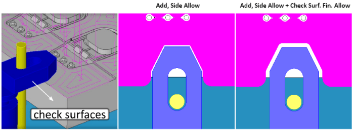
Clearance Allowance for Check Surfaces
The roughing and finishing methods in 3D-Wizard enable users to define boundaries by selecting check surfaces as avoid regions. In this scenario, the toolpath is restricted to remain within the boundaries defined by the selected cut and check surfaces. In version 2024, we have introduced support for an extra clearance allowance specifically applied to check surfaces. As an illustration, this new feature allows users to avoid “pads” with a clearance allowance different from those of the cut surfaces.Solid models have dominated any other form of communication between CAD engineers and EZ-CAM programmers. To benefit from this exchange, beginning with v2021 EZ-CAM has shifted its focus from the traditional approach of requiring curves, which define a path or boundary for each workstep, by moving away to a more sophisticated solution that requires clicking on the model’s features. In doing so, Smart Click can create worksteps in the same time it takes to recognize a hole, chamfer, fillet, pocket, or contour.
-
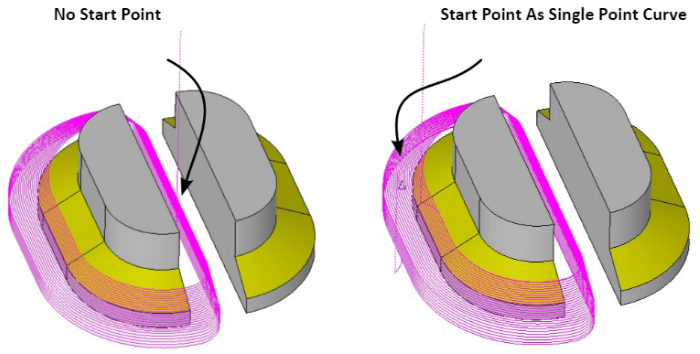
Start Point for Constant-Z Finishing Method
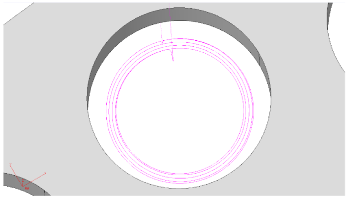
You can now define the start point for the constant-z finishing method within 3D-Wizard. By choosing a single-point curve designated as the “Path Curve,” you can pinpoint the safe location for ramp moves. If you also need to define the machining boundary using a curve, select it as the “2nd path.”
-
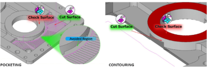
Check Surfaces for Curveless Operations
Check Surface support has been added to curveless pocketing and contouring methods. 2D Silhouette boundaries of the selected check surfaces are used as avoid regions by the new curveless toolpath engine. This feature allows 2,5D toolpath creation for complex shapes even with undercut areas without going through cumbersome geometry / curve creation and editing process.
-
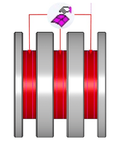
Curveless 4th Axis Wrapping
Check Surface support has been added to curveless pocketing and contouring methods. 2D Silhouette boundaries of the selected check surfaces are used as avoid regions by the new curveless toolpath engine. This feature allows 2,5D toolpath creation for complex shapes even with undercut areas without going through cumbersome geometry / curve creation and editing process.
-
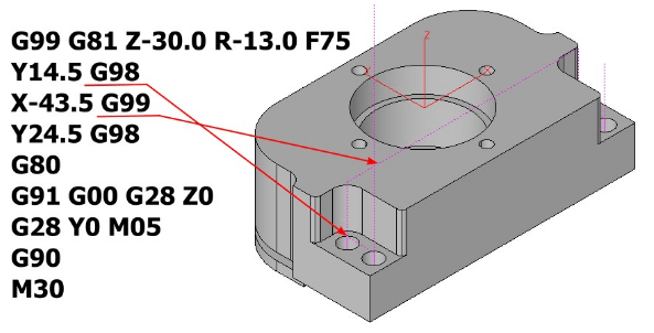
Curveless Drill Operations with Check Z-Clear
In Curveless drill operations, the system performs an automatic check to assess potential obstructions between holes. It intelligently determines where to issue G98 and G99 commands and initiates rapid traverse movements at the Z-rapid plane, ensuring a smooth and efficient drilling process. In some cases where this automatic behavior is not desired it can be turned off using the new “Check Z-Clear” setting in the Holes wizard.
-
Helical Contouring with Multiple-Passes
Multiple-Pass toolpath type creates helical contouring toolpath for closed profiles using the new “Bi-Directional (open) / Helical (closed)” setting in the Contour wizard.
-
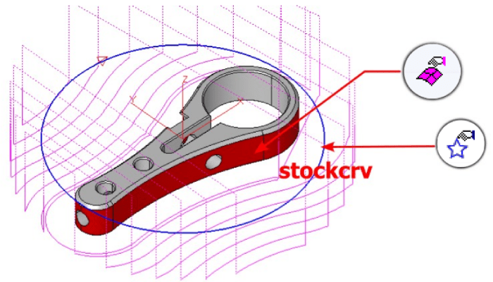
Contour Parallel Roughing with Stock Material
During Contour parallel roughing operations executed with the Multiple-Pass method, there could be instances of “air” moves, where the tool does not engage in cutting when working with stock material of a particular shape. To mitigate this issue, the latest version introduces a feature that enables the selection of a curve labeled “stockcrv” via the “Select Curves” command found in the Machining menu.
-
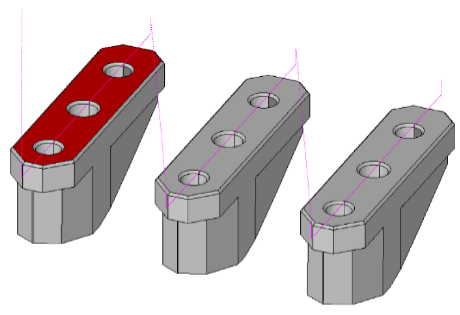
Contour Centerline
A “Contour (Centerline)” option has been introduced to the Face wizard, allowing the creation of a single-pass toolpath along the central line of the shorter sides of the model.
-
Curveless Contouring Depth Input
For Curveless Contouring toolpaths, which rely on the selection of the side walls of the desired profile, there may be instances where it is necessary to position the toolpath at a specific Z-level rather than at the profile’s bottom. In such scenarios, users can include a “single” flat face in the selection of cut surfaces, and the system will utilize this face exclusively for depth calculation.
-
Curveless 4th Axis Indexing Automatic MCS Detection
The curveless toolpath engine now offers support for 4th axis indexing without the need for creating and selecting a Machine Coordinate System (MCS). In EZ-CAM, the origin of the World Coordinate System is taken as the reference point for indexing, and rotation angles are automatically computed based on the orientation of the chosen cut surfaces, as detailed below:
• When hole features are chosen as the cut surfaces, the system establishes the hole axis as the z-axis.
• If all selected flat cut surfaces share a common perpendicular normal vector, the system designates this direction as the z-axis. This category includes the bottom faces of pockets and top surfaces chosen for face-milling.
• When the selected cut surfaces are all parallel to a specific cutting direction, the system designates that direction as the z-axis. This applies to the side walls of through pockets and faces chosen for outside profiling.
• If the chosen cut surfaces do not meet any of the criteria mentioned above, the z-axis of the World Coordinate System remains as the default cutting direction.
-
HSM Trochoidal Pocketing Enhancement
The High-Speed Pocketing toolpath strategy has been enhanced to incorporate larger-radius entry and exit moves into the cutting areas, enabling the utilization of faster feed rates without the risk of overtravel.
-
Hole/Fillet Diameter Display & Input
As we observed numerous parts being programmed, we recognized that the time spent checking hole and fillet diameters, along with manually inputting these values into their respective fields, was causing interruptions in the otherwise seamless workflow of the new system. To address this, we’ve made improvements to the double-click feature. Now, when you double-click on a face, it not only highlights the associated worksteps but also displays diameter information and copies this value to the clipboard and pastes it into the “value” field located on the right side. Furthermore, the hole wizard now includes a new button that enables you to conveniently use this value in the diameter field, like the functionality found in EZ-TURN boundary fields.
-
World on Model / Stock
The “World on Model” command has been updated and is now titled “World on Model/Stock”. It introduces a new option that allows you to position the coordinate system on the stock boundary, rather than the part boundary. Additionally, a new feature has been incorporated, which enables the creation of a Stock Surface, enhancing this crucial feature.
-
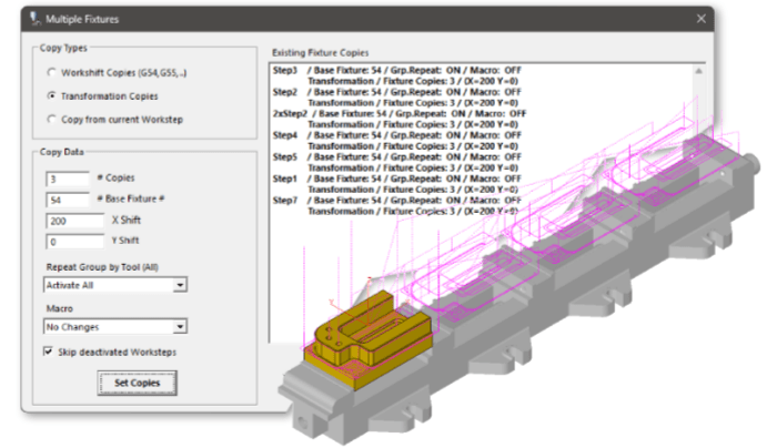
Repeat Manager
The Multiple Fixtures automation command has undergone a significant redesign, now serving as a comprehensive Repeat Management tool. You can either copy “Applied Repetitions” from the current workstep or manually input into the newly added X Shift and Y Shift settings and apply them to all active worksteps. Additionally, the “Delete Copies” function allows you to remove all repetitions from multiple worksteps with a single click.
-
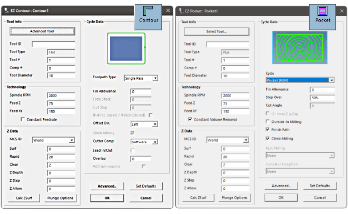
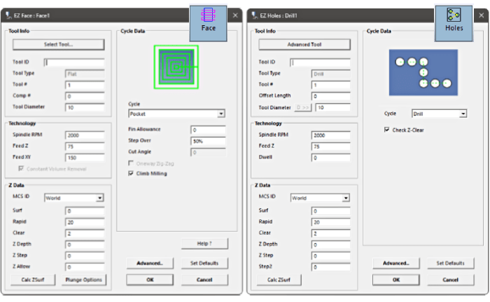
Milling Wizards New Design
The preferred approach for creating 2 ½ D milling worksteps has been to utilize the compact design of Contour, Face, Pocket, and Drill wizards. The latest version enhances their functionality by integrating additional crucial settings, eliminating the necessity to access advanced options. Users particularly appreciate the inclusion of a comprehensive set of tool parameters within the updated design layout.
-
New Template Management
Template support for individual cycle types is now accessible across all mill, turn, and turn-mill machining wizards. Stock material selection can be made either during Stock Setup or in Stock Curve Creation, offering users the flexibility to work with different sets of template files.
These templates, specific to the chosen material, are stored in folders labeled “WorkstepTemplateMetric” followed by the stockMaterialIndex, such as “WorkstepTemplateMetric,” “WorkstepTemplateMetric1,” “WorkstepTemplateMetric2,” and so forth.
Users have the option to edit the templates that come pre-installed with EZ-CAM setup or create new templates by utilizing the “Set Defaults” button available in every wizard. The Workstep ID prompt now includes a new list box for template selection, along with “Delete” and “Rename” buttons, facilitating more efficient template management.
Settings for the currently selected template in the list box are displayed in disabled fields within the data dialogs. You can easily navigate through the list and select the appropriate template before clicking “OK” to create the desired operation.
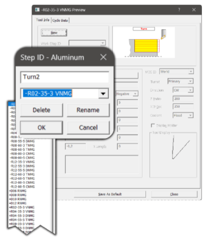
This method is highly recommended for creating worksteps that are ready for toolpath generation after simply selecting the cut surfaces.
-
Check Surfaces for Curveless Operations
Check Surface support has been added to curveless pocketing and contouring methods. 2D Silhouette boundaries of the selected check surfaces are used as avoid regions by the new curveless toolpath engine. This feature allows 2,5D toolpath creation for complex shapes even with undercut areas without going through cumbersome geometry / curve creation and editing process.
-
Curveless 4th Axis Wrapping
Check Surface support has been added to curveless pocketing and contouring methods. 2D Silhouette boundaries of the selected check surfaces are used as avoid regions by the new curveless toolpath engine. This feature allows 2,5D toolpath creation for complex shapes even with undercut areas without going through cumbersome geometry / curve creation and editing process.
-
Curveless Drill Operations with Check Z-Clear
In Curveless drill operations, the system performs an automatic check to assess potential obstructions between holes. It intelligently determines where to issue G98 and G99 commands and initiates rapid traverse movements at the Z-rapid plane, ensuring a smooth and efficient drilling process. In some cases where this automatic behavior is not desired it can be turned off using the new “Check Z-Clear” setting in the Holes wizard.
-
Helical Contouring with Multiple-Passes
Multiple-Pass toolpath type creates helical contouring toolpath for closed profiles using the new “Bi-Directional (open) / Helical (closed)” setting in the Contour wizard.
-
Contour Parallel Roughing with Stock Material
During Contour parallel roughing operations executed with the Multiple-Pass method, there could be instances of “air” moves, where the tool does not engage in cutting when working with stock material of a particular shape. To mitigate this issue, the latest version introduces a feature that enables the selection of a curve labeled “stockcrv” via the “Select Curves” command found in the Machining menu.
-
Contour Centerline
A “Contour (Centerline)” option has been introduced to the Face wizard, allowing the creation of a single-pass toolpath along the central line of the shorter sides of the model.
-
Curveless Contouring Depth Input
For Curveless Contouring toolpaths, which rely on the selection of the side walls of the desired profile, there may be instances where it is necessary to position the toolpath at a specific Z-level rather than at the profile’s bottom. In such scenarios, users can include a “single” flat face in the selection of cut surfaces, and the system will utilize this face exclusively for depth calculation.
-
Curveless 4th Axis Indexing Automatic MCS Detection
The curveless toolpath engine now offers support for 4th axis indexing without the need for creating and selecting a Machine Coordinate System (MCS). In EZ-CAM, the origin of the World Coordinate System is taken as the reference point for indexing, and rotation angles are automatically computed based on the orientation of the chosen cut surfaces, as detailed below:
• When hole features are chosen as the cut surfaces, the system establishes the hole axis as the z-axis.
• If all selected flat cut surfaces share a common perpendicular normal vector, the system designates this direction as the z-axis. This category includes the bottom faces of pockets and top surfaces chosen for face-milling.
• When the selected cut surfaces are all parallel to a specific cutting direction, the system designates that direction as the z-axis. This applies to the side walls of through pockets and faces chosen for outside profiling.
• If the chosen cut surfaces do not meet any of the criteria mentioned above, the z-axis of the World Coordinate System remains as the default cutting direction.
-
HSM Trochoidal Pocketing Enhancement
The High-Speed Pocketing toolpath strategy has been enhanced to incorporate larger-radius entry and exit moves into the cutting areas, enabling the utilization of faster feed rates without the risk of overtravel.
-
Hole/Fillet Diameter Display & Input
As we observed numerous parts being programmed, we recognized that the time spent checking hole and fillet diameters, along with manually inputting these values into their respective fields, was causing interruptions in the otherwise seamless workflow of the new system. To address this, we’ve made improvements to the double-click feature. Now, when you double-click on a face, it not only highlights the associated worksteps but also displays diameter information and copies this value to the clipboard and pastes it into the “value” field located on the right side. Furthermore, the hole wizard now includes a new button that enables you to conveniently use this value in the diameter field, like the functionality found in EZ-TURN boundary fields.
-
World on Model / Stock
The “World on Model” command has been updated and is now titled “World on Model/Stock”. It introduces a new option that allows you to position the coordinate system on the stock boundary, rather than the part boundary. Additionally, a new feature has been incorporated, which enables the creation of a Stock Surface, enhancing this crucial feature.
-
Repeat Manager
The Multiple Fixtures automation command has undergone a significant redesign, now serving as a comprehensive Repeat Management tool. You can either copy “Applied Repetitions” from the current workstep or manually input into the newly added X Shift and Y Shift settings and apply them to all active worksteps. Additionally, the “Delete Copies” function allows you to remove all repetitions from multiple worksteps with a single click.
-
Milling Wizards New Design
The preferred approach for creating 2 ½ D milling worksteps has been to utilize the compact design of Contour, Face, Pocket, and Drill wizards. The latest version enhances their functionality by integrating additional crucial settings, eliminating the necessity to access advanced options. Users particularly appreciate the inclusion of a comprehensive set of tool parameters within the updated design layout.
-
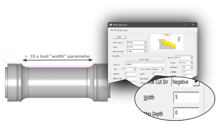
Automatic Groove Detection
The recently introduced automatic groove detection feature generates toolpaths for groove regions suitable for the selected tool. This functionality supports various types of grooves, such as those on the outside, inside, front face, and back face. It’s crucial to configure the tool parameters accurately, as the system avoids regions wider than 10 times the tool’s width. To activate this new feature, ensure that you have not selected any cut surfaces. EZ-TURN operates in a fully automatic mode to detect enclosed groove regions within specified left & right boundaries or based on max-min Z limits of the model. If any cut surfaces are chosen, the automatic detection is disabled, and the system processes the profile of these surfaces as the groove boundary.
-
Skip Groove Option
The Skip Groove option has been revamped not to exclude regions wider than 10 times the tool width parameter. Previously, the tool width was exclusively enabled for groove tools, but it is now available for various tool types when Skip Groove is activated, allowing users to customize the limiting value as needed.
-
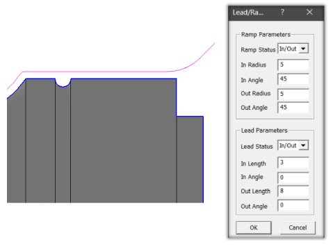
Profile Cycle Ramp and Lead Parameters
The profile cycle now includes support for ramp and lead parameters, akin to the EZ-Mill contouring cycle. This enhancement provides greater flexibility, enabling the extension of finishing passes at both ends to ensure safer entry and exit moves. Additionally, this new feature allows the toolpath to be extended to different limits beyond what is specified by the part boundary.
-
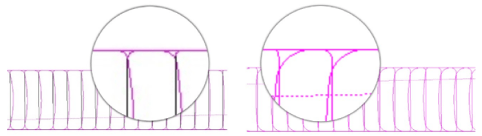
Collision Detection
The new curveless system now includes collision detection for the connection moves between consecutive worksteps. It automatically generates safe travel paths, eliminating the need for manually creating single point curves to define start and end locations.
-
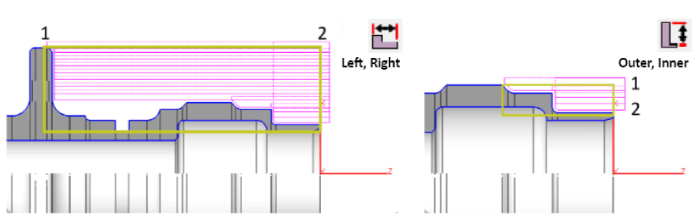
Left-Right and Outer-Inner Boundary Settings
The new template system is specifically designed to minimize manual data entry in the dialogs. As a result, two additional commands had to be incorporated into the Turn Machining tab. These commands are meant for configuring the Left-Right and Outer-Inner boundary settings, which are of utmost importance for the curveless system. Both commands enable users to make graphical selections using point snap options, simplifying the process. The section geometry elements are highlighted in a bold color when the 3/4 section view is activated, making it especially helpful for this purpose.
-
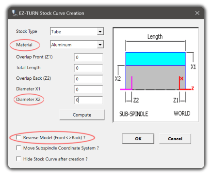
Stock Curve Creation
When importing or transferring solid models in EZ-TURN, the software now includes an automatic process to detect the turning axis and origin point placement. If the automatic placement selects the incorrect side of the part, the new “Reverse Model” option within the “Stock Curve Creation” window can be employed, streamlining the procedure, and eliminating the need for manual adjustments to the origin and world coordinate system orientation.
You will also notice the Compute button in Stock Curve Creation assigns the inner diameter value of the model to the “Diameter X2” field to be used for correct drill size, etc. or to define a “tube” type of stock more easily.
-
New Template Management
Template support for individual cycle types is now accessible across all mill, turn, and turn-mill machining wizards. Stock material selection can be made either during Stock Setup or in Stock Curve Creation, offering users the flexibility to work with different sets of template files.
These templates, specific to the chosen material, are stored in folders labeled “WorkstepTemplateMetric” followed by the stockMaterialIndex, such as “WorkstepTemplateMetric,” “WorkstepTemplateMetric1,” “WorkstepTemplateMetric2,” and so forth.
Users have the option to edit the templates that come pre-installed with EZ-CAM setup or create new templates by utilizing the “Set Defaults” button available in every wizard. The Workstep ID prompt now includes a new list box for template selection, along with “Delete” and “Rename” buttons, facilitating more efficient template management.
Settings for the currently selected template in the list box are displayed in disabled fields within the data dialogs. You can easily navigate through the list and select the appropriate template before clicking “OK” to create the desired operation.
This method is highly recommended for creating worksteps that are ready for toolpath generation after simply selecting the cut surfaces.
-
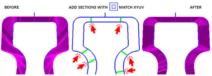
New Match XYUV Curves
Match XYUV Curves command in the Curves menu facilitates the creation of line entities that match sections of upper and lower path curves. When the edge geometry of the solid model cannot provide a precise match, this new command offers a much more straightforward approach for manually creating line entities to define the missing connections, thanks to the special functionality of snap to screen.
-
Die & Punch Wizards Path Directions
The Die and Punch wizard now examines the path directions of the selected curves, ensuring that it generates wire paths on the appropriate side of the part while producing G41/G42 output that matches this orientation.
-
Die & Punch Wizards Thickness Calculation
The Die and Punch wizards now calculate the default value for “thickness” with the correct positive or negative sign based on the curve z-levels and the top and bottom limits of the solid model.
-
Check Surfaces for Curveless Operations
Check Surface support has been added to curveless pocketing and contouring methods. 2D Silhouette boundaries of the selected check surfaces are used as avoid regions by the new curveless toolpath engine. This feature allows 2,5D toolpath creation for complex shapes even with undercut areas without going through cumbersome geometry / curve creation and editing process.
-
Curveless Drill Operations with Check Z-Clear
In Curveless drill operations, the system performs an automatic check to assess potential obstructions between holes. It intelligently determines where to issue G98 and G99 commands and initiates rapid traverse movements at the Z-rapid plane, ensuring a smooth and efficient drilling process. In some cases where this automatic behavior is not desired it can be turned off using the new “Check Z-Clear” setting in the Holes wizard.
-
Helical Contouring with Multiple-Passes
Multiple-Pass toolpath type creates helical contouring toolpath for closed profiles using the new “Bi-Directional (open) / Helical (closed)” setting in the Contour wizard.
-
Contour Parallel Roughing with Stock Material
During Contour parallel roughing operations executed with the Multiple-Pass method, there could be instances of “air” moves, where the tool does not engage in cutting when working with stock material of a particular shape. To mitigate this issue, the latest version introduces a feature that enables the selection of a curve labeled “stockcrv” via the “Select Curves” command found in the Machining menu.
-
Contour Centerline
A “Contour (Centerline)” option has been introduced to the Face wizard, allowing the creation of a single-pass toolpath along the central line of the shorter sides of the model.
-
Curveless Contouring Depth Input
For Curveless Contouring toolpaths, which rely on the selection of the side walls of the desired profile, there may be instances where it is necessary to position the toolpath at a specific Z-level rather than at the profile’s bottom. In such scenarios, users can include a “single” flat face in the selection of cut surfaces, and the system will utilize this face exclusively for depth calculation.
-
HSM Trochoidal Pocketing Enhancement
The High-Speed Pocketing toolpath strategy has been enhanced to incorporate larger-radius entry and exit moves into the cutting areas, enabling the utilization of faster feed rates without the risk of overtravel.
-
Hole/Fillet Diameter Display & Input
As we observed numerous parts being programmed, we recognized that the time spent checking hole and fillet diameters, along with manually inputting these values into their respective fields, was causing interruptions in the otherwise seamless workflow of the new system. To address this, we’ve made improvements to the double-click feature. Now, when you double-click on a face, it not only highlights the associated worksteps but also displays diameter information and copies this value to the clipboard and pastes it into the “value” field located on the right side. Furthermore, the hole wizard now includes a new button that enables you to conveniently use this value in the diameter field, like the functionality found in EZ-TURN boundary fields.
-
World on Model / Stock
The “World on Model” command has been updated and is now titled “World on Model/Stock”. It introduces a new option that allows you to position the coordinate system on the stock boundary, rather than the part boundary. Additionally, a new feature has been incorporated, which enables the creation of a Stock Surface, enhancing this crucial feature.
-
Repeat Manager
The Multiple Fixtures automation command has undergone a significant redesign, now serving as a comprehensive Repeat Management tool. You can either copy “Applied Repetitions” from the current workstep or manually input into the newly added X Shift and Y Shift settings and apply them to all active worksteps. Additionally, the “Delete Copies” function allows you to remove all repetitions from multiple worksteps with a single click.
-
Milling Wizards New Design
The preferred approach for creating 2 ½ D milling worksteps has been to utilize the compact design of Contour, Face, Pocket, and Drill wizards. The latest version enhances their functionality by integrating additional crucial settings, eliminating the necessity to access advanced options. Users particularly appreciate the inclusion of a comprehensive set of tool parameters within the updated design layout.
-
New Template Management
Template support for individual cycle types is now accessible across all mill, turn, and turn-mill machining wizards. Stock material selection can be made either during Stock Setup or in Stock Curve Creation, offering users the flexibility to work with different sets of template files.
These templates, specific to the chosen material, are stored in folders labeled “WorkstepTemplateMetric” followed by the stockMaterialIndex, such as “WorkstepTemplateMetric,” “WorkstepTemplateMetric1,” “WorkstepTemplateMetric2,” and so forth.
Users have the option to edit the templates that come pre-installed with EZ-CAM setup or create new templates by utilizing the “Set Defaults” button available in every wizard. The Workstep ID prompt now includes a new list box for template selection, along with “Delete” and “Rename” buttons, facilitating more efficient template management.
Settings for the currently selected template in the list box are displayed in disabled fields within the data dialogs. You can easily navigate through the list and select the appropriate template before clicking “OK” to create the desired operation.
This method is highly recommended for creating worksteps that are ready for toolpath generation after simply selecting the cut surfaces.
-
Automatic Groove Detection
The recently introduced automatic groove detection feature generates toolpaths for groove regions suitable for the selected tool. This functionality supports various types of grooves, such as those on the outside, inside, front face, and back face. It’s crucial to configure the tool parameters accurately, as the system avoids regions wider than 10 times the tool’s width. To activate this new feature, ensure that you have not selected any cut surfaces. EZ-TURN operates in a fully automatic mode to detect enclosed groove regions within specified left & right boundaries or based on max-min Z limits of the model. If any cut surfaces are chosen, the automatic detection is disabled, and the system processes the profile of these surfaces as the groove boundary.
-
Skip Groove Option
The Skip Groove option has been revamped not to exclude regions wider than 10 times the tool width parameter. Previously, the tool width was exclusively enabled for groove tools, but it is now available for various tool types when Skip Groove is activated, allowing users to customize the limiting value as needed.
-
Profile Cycle Ramp and Lead Parameters
The profile cycle now includes support for ramp and lead parameters, akin to the EZ-Mill contouring cycle. This enhancement provides greater flexibility, enabling the extension of finishing passes at both ends to ensure safer entry and exit moves. Additionally, this new feature allows the toolpath to be extended to different limits beyond what is specified by the part boundary.
-
Collision Detection
The new curveless system now includes collision detection for the connection moves between consecutive worksteps. It automatically generates safe travel paths, eliminating the need for manually creating single point curves to define start and end locations.
-
Left-Right and Outer-Inner Boundary Settings
The new template system is specifically designed to minimize manual data entry in the dialogs. As a result, two additional commands had to be incorporated into the Turn Machining tab. These commands are meant for configuring the Left-Right and Outer-Inner boundary settings, which are of utmost importance for the curveless system. Both commands enable users to make graphical selections using point snap options, simplifying the process. The section geometry elements are highlighted in a bold color when the 3/4 section view is activated, making it especially helpful for this purpose.
-
Stock Curve Creation
When importing or transferring solid models in EZ-TURN, the software now includes an automatic process to detect the turning axis and origin point placement. If the automatic placement selects the incorrect side of the part, the new “Reverse Model” option within the “Stock Curve Creation” window can be employed, streamlining the procedure, and eliminating the need for manual adjustments to the origin and world coordinate system orientation.
You will also notice the Compute button in Stock Curve Creation assigns the inner diameter value of the model to the “Diameter X2” field to be used for correct drill size, etc. or to define a “tube” type of stock more easily.
-
New Template Management
Template support for individual cycle types is now accessible across all mill, turn, and turn-mill machining wizards. Stock material selection can be made either during Stock Setup or in Stock Curve Creation, offering users the flexibility to work with different sets of template files.
These templates, specific to the chosen material, are stored in folders labeled “WorkstepTemplateMetric” followed by the stockMaterialIndex, such as “WorkstepTemplateMetric,” “WorkstepTemplateMetric1,” “WorkstepTemplateMetric2,” and so forth.
Users have the option to edit the templates that come pre-installed with EZ-CAM setup or create new templates by utilizing the “Set Defaults” button available in every wizard. The Workstep ID prompt now includes a new list box for template selection, along with “Delete” and “Rename” buttons, facilitating more efficient template management.
Settings for the currently selected template in the list box are displayed in disabled fields within the data dialogs. You can easily navigate through the list and select the appropriate template before clicking “OK” to create the desired operation.
This method is highly recommended for creating worksteps that are ready for toolpath generation after simply selecting the cut surfaces.
-
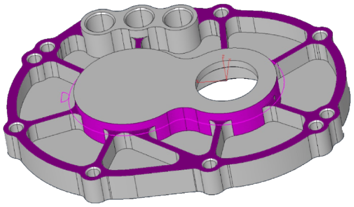
MILL Pro » Clearance Allowance for Check Surfaces
The roughing and finishing methods in 3D-Wizard enable users to define boundaries by selecting check surfaces as avoid regions. In this scenario, the toolpath is restricted to remain within the boundaries defined by the selected cut and check surfaces. In version 2024, we have introduced support for an extra clearance allowance specifically applied to check surfaces. As an illustration, this new feature allows users to avoid “pads” with a clearance allowance different from those of the cut surfaces.Solid models have dominated any other form of communication between CAD engineers and EZ-CAM programmers. To benefit from this exchange, beginning with v2021 EZ-CAM has shifted its focus from the traditional approach of requiring curves, which define a path or boundary for each workstep, by moving away to a more sophisticated solution that requires clicking on the model’s features. In doing so, Smart Click can create worksteps in the same time it takes to recognize a hole, chamfer, fillet, pocket, or contour.
-
MILL Pro » Start Point for Constant-Z Finishing Method
You can now define the start point for the constant-z finishing method within 3D-Wizard. By choosing a single-point curve designated as the “Path Curve,” you can pinpoint the safe location for ramp moves. If you also need to define the machining boundary using a curve, select it as the “2nd path.”
-
MILL Pro – MILL – MILL Express » Check Surfaces for Curveless Operations
Check Surface support has been added to curveless pocketing and contouring methods. 2D Silhouette boundaries of the selected check surfaces are used as avoid regions by the new curveless toolpath engine. This feature allows 2,5D toolpath creation for complex shapes even with undercut areas without going through cumbersome geometry / curve creation and editing process.
-
MILL Pro – MILL » Curveless 4th Axis Wrapping
Check Surface support has been added to curveless pocketing and contouring methods. 2D Silhouette boundaries of the selected check surfaces are used as avoid regions by the new curveless toolpath engine. This feature allows 2,5D toolpath creation for complex shapes even with undercut areas without going through cumbersome geometry / curve creation and editing process.
-
MILL Pro – MILL – MILL Express » Curveless Drill Operations with Check Z-Clear
In Curveless drill operations, the system performs an automatic check to assess potential obstructions between holes. It intelligently determines where to issue G98 and G99 commands and initiates rapid traverse movements at the Z-rapid plane, ensuring a smooth and efficient drilling process. In some cases where this automatic behavior is not desired it can be turned off using the new “Check Z-Clear” setting in the Holes wizard.
-
MILL Pro – MILL – MILL Express » Helical Contouring with Multiple-Passes
Multiple-Pass toolpath type creates helical contouring toolpath for closed profiles using the new “Bi-Directional (open) / Helical (closed)” setting in the Contour wizard.
-
MILL Pro – MILL – MILL Express » Contour Parallel Roughing with Stock Material
During Contour parallel roughing operations executed with the Multiple-Pass method, there could be instances of “air” moves, where the tool does not engage in cutting when working with stock material of a particular shape. To mitigate this issue, the latest version introduces a feature that enables the selection of a curve labeled “stockcrv” via the “Select Curves” command found in the Machining menu.
-
MILL Pro – MILL – MILL Express » Contour Centerline
A “Contour (Centerline)” option has been introduced to the Face wizard, allowing the creation of a single-pass toolpath along the central line of the shorter sides of the model.
-
MILL Pro – MILL – MILL Express » Curveless Contouring Depth Input
For Curveless Contouring toolpaths, which rely on the selection of the side walls of the desired profile, there may be instances where it is necessary to position the toolpath at a specific Z-level rather than at the profile’s bottom. In such scenarios, users can include a “single” flat face in the selection of cut surfaces, and the system will utilize this face exclusively for depth calculation.
-
MILL Pro – MILL » Curveless 4th Axis Indexing Automatic MCS Detection
The curveless toolpath engine now offers support for 4th axis indexing without the need for creating and selecting a Machine Coordinate System (MCS). In EZ-CAM, the origin of the World Coordinate System is taken as the reference point for indexing, and rotation angles are automatically computed based on the orientation of the chosen cut surfaces, as detailed below:
• When hole features are chosen as the cut surfaces, the system establishes the hole axis as the z-axis.
• If all selected flat cut surfaces share a common perpendicular normal vector, the system designates this direction as the z-axis. This category includes the bottom faces of pockets and top surfaces chosen for face-milling.
• When the selected cut surfaces are all parallel to a specific cutting direction, the system designates that direction as the z-axis. This applies to the side walls of through pockets and faces chosen for outside profiling.
• If the chosen cut surfaces do not meet any of the criteria mentioned above, the z-axis of the World Coordinate System remains as the default cutting direction.
-
MILL Pro – MILL – MILL Express » HSM Trochoidal Pocketing Enhancement
The High-Speed Pocketing toolpath strategy has been enhanced to incorporate larger-radius entry and exit moves into the cutting areas, enabling the utilization of faster feed rates without the risk of overtravel.
-
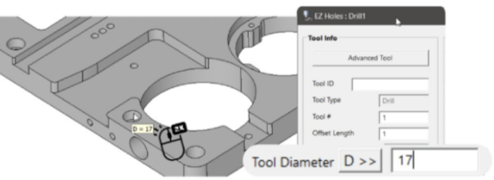
MILL Pro – MILL – MILL Express » Hole/Fillet Diameter Display & Input
As we observed numerous parts being programmed, we recognized that the time spent checking hole and fillet diameters, along with manually inputting these values into their respective fields, was causing interruptions in the otherwise seamless workflow of the new system. To address this, we’ve made improvements to the double-click feature. Now, when you double-click on a face, it not only highlights the associated worksteps but also displays diameter information and copies this value to the clipboard and pastes it into the “value” field located on the right side. Furthermore, the hole wizard now includes a new button that enables you to conveniently use this value in the diameter field, like the functionality found in EZ-TURN boundary fields.
-
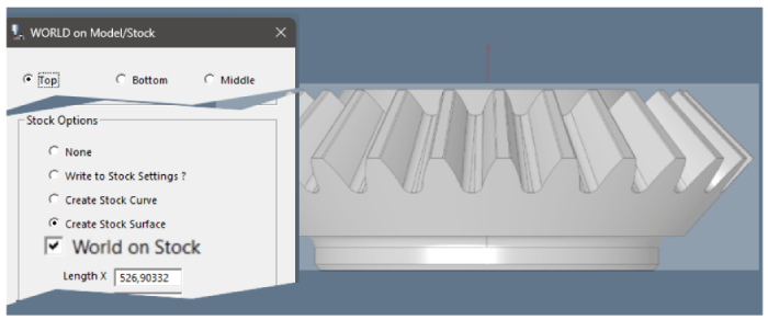
MILL Pro – MILL – MILL Express » World on Model / Stock
The “World on Model” command has been updated and is now titled “World on Model/Stock”. It introduces a new option that allows you to position the coordinate system on the stock boundary, rather than the part boundary. Additionally, a new feature has been incorporated, which enables the creation of a Stock Surface, enhancing this crucial feature.
-
MILL Pro – MILL – MILL Express » Repeat Manager
The Multiple Fixtures automation command has undergone a significant redesign, now serving as a comprehensive Repeat Management tool. You can either copy “Applied Repetitions” from the current workstep or manually input into the newly added X Shift and Y Shift settings and apply them to all active worksteps. Additionally, the “Delete Copies” function allows you to remove all repetitions from multiple worksteps with a single click.
-
MILL Pro – MILL – MILL Express » Milling Wizards New Design
The preferred approach for creating 2 ½ D milling worksteps has been to utilize the compact design of Contour, Face, Pocket, and Drill wizards. The latest version enhances their functionality by integrating additional crucial settings, eliminating the necessity to access advanced options. Users particularly appreciate the inclusion of a comprehensive set of tool parameters within the updated design layout.
-
TURN – TURN Express » Automatic Groove Detection
The recently introduced automatic groove detection feature generates toolpaths for groove regions suitable for the selected tool. This functionality supports various types of grooves, such as those on the outside, inside, front face, and back face. It’s crucial to configure the tool parameters accurately, as the system avoids regions wider than 10 times the tool’s width. To activate this new feature, ensure that you have not selected any cut surfaces. EZ-TURN operates in a fully automatic mode to detect enclosed groove regions within specified left & right boundaries or based on max-min Z limits of the model. If any cut surfaces are chosen, the automatic detection is disabled, and the system processes the profile of these surfaces as the groove boundary.
-
TURN – TURN Express » Skip Groove Option
The Skip Groove option has been revamped not to exclude regions wider than 10 times the tool width parameter. Previously, the tool width was exclusively enabled for groove tools, but it is now available for various tool types when Skip Groove is activated, allowing users to customize the limiting value as needed.
-
TURN – TURN Express » Profile Cycle Ramp and Lead Parameters
The profile cycle now includes support for ramp and lead parameters, akin to the EZ-Mill contouring cycle. This enhancement provides greater flexibility, enabling the extension of finishing passes at both ends to ensure safer entry and exit moves. Additionally, this new feature allows the toolpath to be extended to different limits beyond what is specified by the part boundary.
-
TURN – TURN Express » Collision Detection
The new curveless system now includes collision detection for the connection moves between consecutive worksteps. It automatically generates safe travel paths, eliminating the need for manually creating single point curves to define start and end locations.
-
TURN – TURN Express » Left-Right and Outer-Inner Boundary Settings
The new template system is specifically designed to minimize manual data entry in the dialogs. As a result, two additional commands had to be incorporated into the Turn Machining tab. These commands are meant for configuring the Left-Right and Outer-Inner boundary settings, which are of utmost importance for the curveless system. Both commands enable users to make graphical selections using point snap options, simplifying the process. The section geometry elements are highlighted in a bold color when the 3/4 section view is activated, making it especially helpful for this purpose.
-
TURN – TURN Express » Stock Curve Creation
When importing or transferring solid models in EZ-TURN, the software now includes an automatic process to detect the turning axis and origin point placement. If the automatic placement selects the incorrect side of the part, the new “Reverse Model” option within the “Stock Curve Creation” window can be employed, streamlining the procedure, and eliminating the need for manual adjustments to the origin and world coordinate system orientation.
You will also notice the Compute button in Stock Curve Creation assigns the inner diameter value of the model to the “Diameter X2” field to be used for correct drill size, etc. or to define a “tube” type of stock more easily.
-
MILL Pro – MILL – MILL Express – TURN – TURN Express » New Template Management
Template support for individual cycle types is now accessible across all mill, turn, and turn-mill machining wizards. Stock material selection can be made either during Stock Setup or in Stock Curve Creation, offering users the flexibility to work with different sets of template files.
These templates, specific to the chosen material, are stored in folders labeled “WorkstepTemplateMetric” followed by the stockMaterialIndex, such as “WorkstepTemplateMetric,” “WorkstepTemplateMetric1,” “WorkstepTemplateMetric2,” and so forth.
Users have the option to edit the templates that come pre-installed with EZ-CAM setup or create new templates by utilizing the “Set Defaults” button available in every wizard. The Workstep ID prompt now includes a new list box for template selection, along with “Delete” and “Rename” buttons, facilitating more efficient template management.
Settings for the currently selected template in the list box are displayed in disabled fields within the data dialogs. You can easily navigate through the list and select the appropriate template before clicking “OK” to create the desired operation.
This method is highly recommended for creating worksteps that are ready for toolpath generation after simply selecting the cut surfaces.
-
EDM » New Match XYUV Curves
Match XYUV Curves command in the Curves menu facilitates the creation of line entities that match sections of upper and lower path curves. When the edge geometry of the solid model cannot provide a precise match, this new command offers a much more straightforward approach for manually creating line entities to define the missing connections, thanks to the special functionality of snap to screen.
-
EDM » Die & Punch Wizards Path Directions
The Die and Punch wizard now examines the path directions of the selected curves, ensuring that it generates wire paths on the appropriate side of the part while producing G41/G42 output that matches this orientation.
-
EDM » Die & Punch Wizards Thickness Calculation
The Die and Punch wizards now calculate the default value for “thickness” with the correct positive or negative sign based on the curve z-levels and the top and bottom limits of the solid model.